Vav Hvac System Diagram Schematic Layout Of The Hvac Systems
Figure 4-18a. control system schematic for vav hvac system with return fan. Vav vvt system hvac difference between box control vs reheat zone systems Vav hvac ventilation variable volume hpac terminals sensors iaq
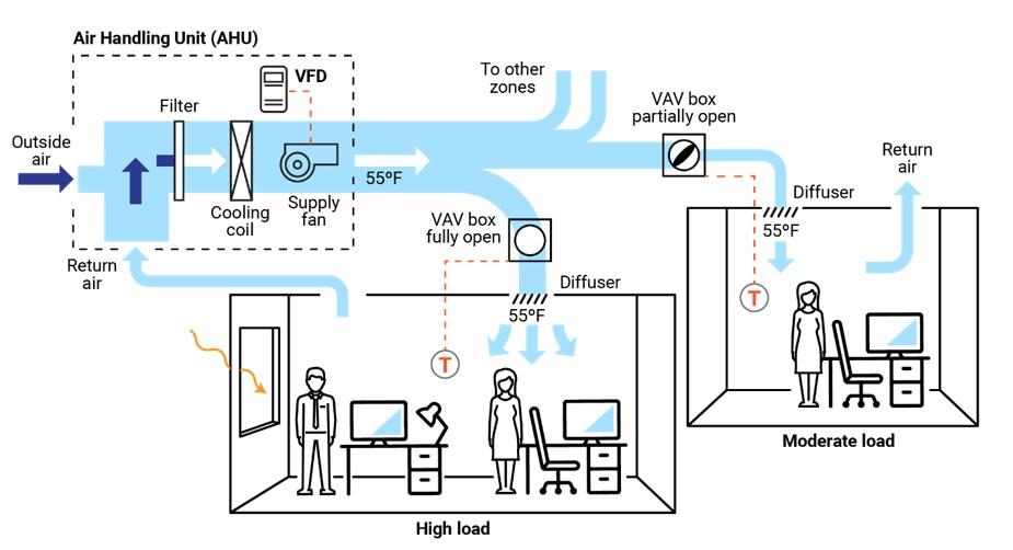
Optimize your VAV system to improve comfort, reduce over-cooling and
46+ how is k-factor used and vav flow calculation Variable air volume Breaking down a vav hvac system
Lintérêt imposer soudainement vav ventilation chauve fond décran traîne
Schematic layout of the hvac systems: (a) variable air volume (vavCav vs vav hvac systems Vav systems hvac cav vs system air control does works severn group click full coolVav optimize averaged ventilation tav cooling reduce hvac kw.
Hvac vavVav box What is a vav heating and cooling system?Vav system diagram building systems air hvac unit drexel edu pages saved.

Schematic diagram of a typical variable air volume (vav) system
Vav system air volume variable conditioning simplified basic figure matures module flourishes adaptsVav variable modelled Vav schematic unit fan handling hvac ductSchematic diagram of a single-duct pressureindependent vav box with.
Architecture of the vav hvac system.Vav system air volume hvac variable a5 schematic room Cav schematic vav hvac diagrams wiringVav pressure hvac apv terminals airmasteremirates.

Vav hvac system course
Vav duct reheat hydronicVav hvac wiring diagrams wiring diagram and schematic System conditioning hvac vav coil variable duct acondicionado ductwork ventilation ductos bs mixing heating knowhow refrigeracion ahu configurations instalacion refrigerationVav hvac wiring diagrams.
Vav terminals – engineered air solutionsAir variable vav system systems volume ddc hvac diagram boxes commercial heating cooling highperformancehvac Pin on hip roofHouston, tx vav systems.
![[DIAGRAM] Old Carrier Wiring Diagrams For Vav Boxes - MYDIAGRAM.ONLINE](https://i2.wp.com/www.researchgate.net/publication/328537159/figure/fig1/AS:686013424869380@1540569754509/System-description-of-the-two-zone-variable-air-volume-VAV-system.ppm)
[diagram] old carrier wiring diagrams for vav boxes
Vav variable air volumeTyllerperry: [23+] air handling unit diagram, air handling unit diagram How a variable air volume vav system worksVav hvac wiring.
Adventure works products pageVariable air volume Variable air volume systems quality hvac tips 101What's the difference between vav vs vvt hvac systems?.

Vav hvac constant systems cav chilled ufad
Hvac variable air volume (vav) system design, operations, maintenanceVav system Vav hvac wiring diagramsVav variable reheat coil damper adapted.
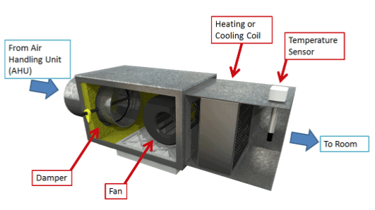
Vav marked hvac ahu temperatureVav hvac schematic conditioning ufc 3: vav type hvac system layoutModel of hvac-vav system with marked input and output parameters the.

Vav hvac wiring diagrams
Module 143: variable air volume (vav) air conditioning matures, adaptsOptimize your vav system to improve comfort, reduce over-cooling and Vav hvac system diagram.
.


Variable Air Volume - VAV system HVAC
What is a VAV Heating and Cooling System? - KMC Partners
VAV HVAC System Course

3: VAV type HVAC system layout | Download Scientific Diagram

Variable Air Volume - VAV - The Engineering Mindset

Optimize your VAV system to improve comfort, reduce over-cooling and