V To I Converter Circuit Diagram Volt Wiring Charging Transf
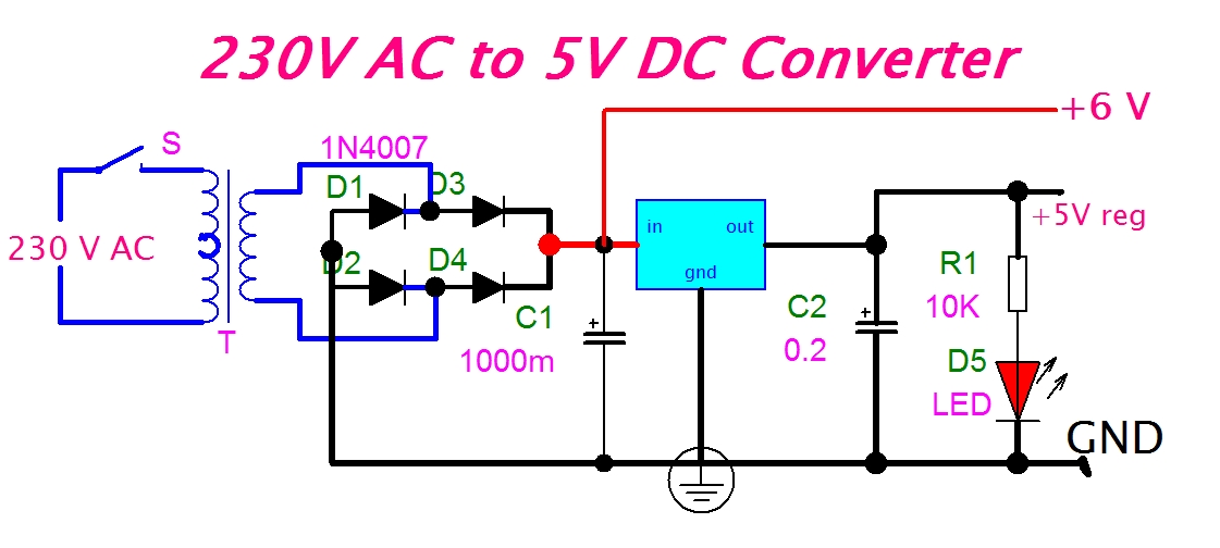
Eeetricks.blogspot.com: 230v ac to 5v dc converter circuit diagram The v-i conversion circuit Build a 12v to 9 or 6 v converter circuit diagram
Solved 1 Compute the values of V, V, and I for Circuit 1 and | Chegg.com
Current converter voltage source input electronics amp op circuit tutorial resistor rf applied since here through V-to-i circuit diagram. Schematic converter
I to v converter using op amp circuit diagram
Solved in the circuit diagram provided, you have a voltageConverter loop circuit 12v to 5v converter circuitConventional v–i converter structures with (a) voltage feedback loop.
12v circuit converter diagram build dc supply power diode car gr next electrical230v dc ac circuit converter 5v diagram Circuit diagram of a current-to-voltage converter (ivc) where r f isCircuit diagram of the v-i converter..

Circuit simple diagram 16v converter
F to v converter circuit diagramSchematic circuit diagram of i-v converter. I-v converter circuitCircuit diagram of v/i converter and loop filter..
Simple 12 -16v converter circuit diagramV to v transformer wiring diagram Voltage to current converter (v to i converter)V-i converter which does not require balanced inputs..

Vcii based i to v converter [14]
Converter floating groundedV/i converter circuit. Current to voltage converterElectrical4u circuits analog.
Solved ii- 1) draw the circuit of a v-i converter and deriveA simplified circuit diagram of the v-i converter. Volt wiring charging transformer capacitorV i and i v converter.
Current to voltage converter(i to v) » op-amp tutorial
(a) the schematic circuit of the i-v converter. (b) the schematicI / v conversion circuit V to i converter in hindiIvc capacitance parallel resistance.
(a) the schematic circuit of the i-v converter. (b) the schematicWhat is voltage to current converter (v to i converter) using op-amp Solved 1 compute the values of v, v, and i for circuit 1 and(a) schematic illustration and corresponding circuit diagram of an.

12v ac to dc converter circuit diagram
12v ac to dc converter circuit diagramCircuit diagram of the i-v converter. .
.


i to v converter using op amp circuit diagram - Circuit Diagram

Simple 12 -16V Converter Circuit Diagram

Solved 1 Compute the values of V, V, and I for Circuit 1 and | Chegg.com

Voltage to Current Converter (V to I Converter) | Electrical4U

F To V Converter Circuit Diagram

V/I converter circuit. | Download Scientific Diagram

Solved II- 1) Draw the circuit of a V-I converter and derive | Chegg.com